

Advancing Solid-State Transformers Performance via Modulations and Interconnections: Implications for EMC Impact
Solid-state transformer (SST)-based substation systems can link renewables, energy storage systems, and asynchronous systems; carry out FACTS operations; and offer more flexible control [Iov, Florin, et al, 2009]. Due to the advancement of power electronics devices and transformer core materials, they can be potential solutions for replacing the conventional low-frequency transformer-based systems. Nowadays and in the future, modern electric systems are composed of different types of energy sources, such as solar, energy storage, wind, and fuel cells. These systems can be configured based on a specific application to control, share and manage the needed energy/power at each port using an SST, Fig. 1.
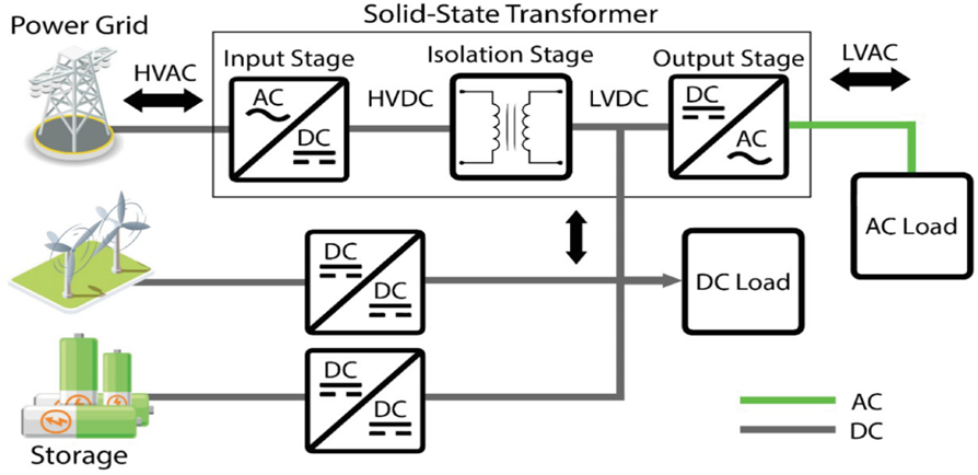
Photo- reference: Agarwala, Amrita, et al. "Towards next generation power grid transformer for renewables: Technology review." Engineering Reports 6.4 (2024): e12848.
Fig. 1: Overview of solid-state (SST) infrastructure.
Although SST was patented in the early 1960s, electromagnetic compatibility (EMC) is still one of the key challenges due to the development of fast-switching and high-frequency power electronics devices, such as the wide-bandgap devices. Identifying the sources, coupling paths, and victims of electromagnetic interference on a complex system, such as a railway substation system, which is composed of several systems with different operating voltage and frequency levels, is very challenging. The best solution is to consider EMC starting a design phase and ensuring component-level compliance before system-level compliance to save time and money.
Several researchers have been working to improve the efficiency of SST, considering different techniques such as modulation methods. By adding an inner-phase shift using triple-phase shift (TPS) or double-phase shift (DPS) modulations, the circulating currents of an SST can be minimised. However, the additional inner phase shifts increase the switching events. One of the main causes of common-mode electromagnetic interference (EMI) is the displacement currents, which occur during the switching event of the power electronics device due to the high dV/dt. This current will flow to the common ground plane through capacitive coupling and cause common-mode emission. A comparison of single-phase shift (SPS) and TPS modulations is shown in Fig.2. An SST with SPS modulation has better common-mode EMI but worse circulating current. On the contrary, an SST with TPS modulation has better efficiency but worse conducted EMI due to the higher number of switching events. This can be easily analysed by checking the current through the transformer interwinding capacitances.
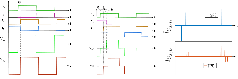
Fig. 2: SST modulation techniques- (a). SPS, and (b). TPS. (c). Current through transformer interwinding capacitance: Using SPS modulation - top figure with blue line and using TPS modulation - bottom figure with red line.
In addition, the impacts of the modulation techniques on the collector-emitter voltage and common-mode current are shown in Fig. 3. Due to the inner-phase shifts, TPS modulation has an additional ringing on the collector-emitter voltage and higher CM current.
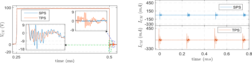
Fig. 3: Impact of modulation techniques on: Collector-emitter voltage, VCE (left side), conducted CM current (right side).
Parts of this work are published in the IEEE Open Journal of Power Electronics (https://ieeexplore.ieee.org/document/11168254) and the PEMD 2024 conference (https://ieeexplore.ieee.org/document/10663578 ).
To increase the power level, multicell SSTs are used, which can be configured as input-parallel output-series, input-parallel output-parallel, input-series output-parallel or input-series output-series depending on the required voltage and current. Since the EMI of these different configurations is not the same, the main sources, coupling paths and mitigation techniques must be identified for each configuration. One of the mitigation techniques is to make the switching patterns of two SSTs complementary to achieve a dV/dt cancellation. The second method is to use a combination of modulations and interconnections with complementary switching. By doing this, efficiency and EMI can be improved. For example, if there are an even number of SST cells, it can be configured to have complementary switching to reduce the CM EMI and improve efficiency using TPS modulation. For an odd number of SST cells, the even number of cells can be configured to have complementary switching with TPS modulation and the remaining one with SPS modulation to improve both EMI and efficiency. For further information, you can refer to a paper presented at the EPE25 conference and published in https://utc.hal.science/hal-05081828/ . This finding is experimentally validated using the setup shown in Fig. 4. Stay tuned for future publication updates.
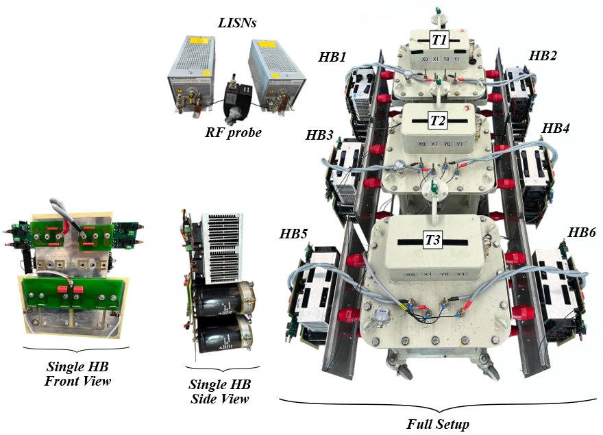
Fig. 4: Experimental setup for a system with three SSTs. Photo: Credit - Peyman (ESR09).